POWER TRAIN
DISASSEMBLY AND ASSEMBLY
TM 5-3805-263-14&P-2
TRANSMISSION HYDRAULIC CONTROL VALVES
27. Remove the snap ring from valve spool (44)
with tool (C).
28. Remove retainer (49), spring (51), and
plunger (50) from the valve spool.
29. Remove pin (48) from the spool.
30.
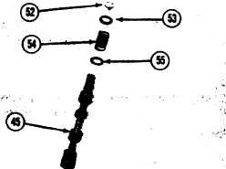
31.
Put the spring in compression and remove
snap ring (52) with tool(B).
Remove washer (53), spring (54), and
washer (55) from valve spool (45).
ASSEMBLE TRANSMISSION HYDRAULIC
CONTROL VALVES
Tools Needed
A
B
C
lP1854
Pliers
1
lP1959
Pliers
1
FT1195
Pliers
1
1.
2.
3.
4.
5.
6.
7.
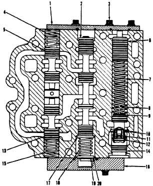
Put valve spools (5) and (13) into position
in the modulating control valve. Put springs
(4) and (15) in position on the spools.
Put washer (17), spring (18), and washer
(20) in position on the spool. Put the spring
in compression and install snap ring (19)
with tool(B).
Put valve spool (2) in position in the valve.
Put two springs (7) in position on the spacer
and piston (6). Put piston (6) into position
in the valve.
Put plunger (10), spring (11) and retainer
(12) into position in the valve spool. Install
the snap ring in the spool with tool (C). Put
pin (8) and spacers (9) in position on the
spool. Put the slug into position in the
spool.
Put valve spool (14) into position in the
valve.
Install the O-ring seals in the two covers.
Put covers (1) and (16) in position on the
valve. Install bolts (3) that hold the two
covers. Tighten bolts (3) to a torque of
22 ± 3 lb.ft. (3.0 ± 0.4 mkg).
2-120