POWER TRAIN
DISASSEMBLY AND ASSEMBLY
TM 5-3805-263-14&P-2
TRANSMISSION GEARS
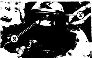
40. Lower the temperature of bearing cup (38).
Install the bearing cup in the cage for the
input gear shaft.
41. Install the original amount of shims (37) on
the cage.
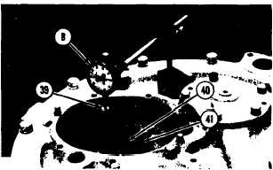
42. Put cage (40) in position on the cover.
Install bolts (41) and the lockwashers that
hold it. Tighten the bolts evenly.
43. Install a 3/8”-16 NC x 4” long bolt (39) in
the shaft.
44. Put tooling (B) in position as shown. Check
the end clearance of the input gear shaft by
moving the shaft up and down from the
bottom side of the case. The end clearance
must be .002 to .006 in. (0.05 to 0.15 mm).
Add or remove shims from under cage (40)
to get the correct clearance. Remove tooling
(B) and the bolt from the shaft.
45. Install the guide in the end of the input gear
shaft.
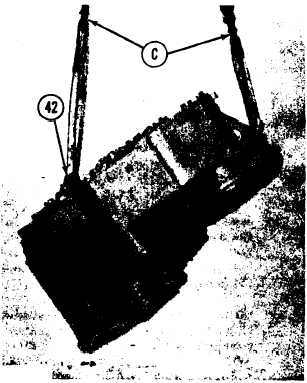
46. Remove two bolts from the cover. Install
two 1/2”-13 NC forged eyebolts (42) in
their place. Fasten tool (C) to the eyebolts
and to the transmission.
47. Turn the transmission with tool (C) to an
up position and install it on tool (D).
48. Remove the two eyebolts and the hoist.
Install the two bolts and lockwashers in the
cover.
49. Put the coupling for the flywheel in posi-
tion on the input gear shaft. Install the
retainer and the bolt that holds the retainer.
Tighten the bolt to a torque of 85 ± 5 lb. ft.
(11.8 ± 0.7 mkg).
end by:
a) install transmission
2-116