POWER TRAIN
DISASSEMBLY AND ASSEMBLY
TM 5-3805-263-14&P-2
TRANSMISSION HYDRAULIC CONTROL VALVES
20.
21.
22.
23.
24.
25.
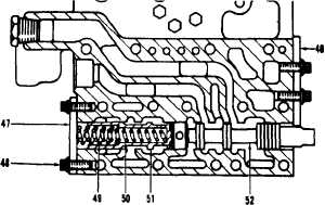
Put valve spool (52) into position in the
directional control valve.
Put valve spool (5 1) into position in the
valve. Put springs (50) and (49) into posi-
tion in the spool.
Put plates (46) and (47) in position on the
valve. Install bolts (48) that hold the two
plates. Tighten bolts (48) to a torque of
22 ± 3 lb.ft. (3.0 ± 0.4 mkg).
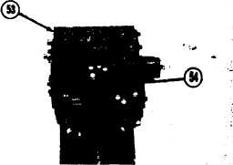
Put directional control valve (53) in posi-
tion on the differential control valve.
Install bolts (54). Tighten bolts (54) to a
torque of 22 ± 3 lb.ft. (3.0 ± 0.4 mkg).
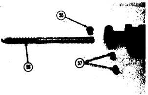
Put detents (57) in position in the pilot
valve. Install the pin that holds the detent in
the valve.
26. Put valve spool (56) into position in the
valve.
27.
28.
29.
Install the O-ring seal on the stop. Install
stop (55) in the valve.
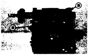
Put pilot valve (58) in position on the direc-
tional control valve.
Install bolts (59). Tighten bolts to a torque
of 22 ± 3 lb.ft. (3.0 ± 0.4 mkg).
2-122