POWER TRAIN
DISASSEMBLY AND ASSEMBLY
TRANSMISSION GEARS
TM 5-3805-263-14&P-2
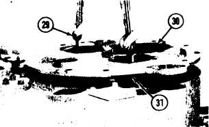
31. Install two 3/8”-16 NC forged eyebolts (29)
in cover (30). Fasten a hoist to the eyebolts.
32. Lift the cover. Install O-ring seal (3 1) on the
cover. Put the cover in position on the case.
NOTE: The dowel in the idler gear shaft must be in
alignment with the groove (slot) in the bottom of
the cover.
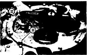
33. Install bolts (33) and the lockwashers that
hold the cover to the case.
34. Install the O-ring seal and retainer (32).
Install the bolt that holds the retainer and
tighten it to a torque of 85 ± 5 lb. ft. (11.8
± 0.7 mkg).
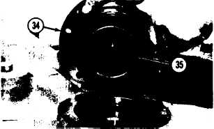
NOTE: Do Steps 35 through 38 for each cage.
35.
36.
37.
38.
39.
Lower the temperature of bearing cup (35).
Install the bearing cup in cage (34). Install
the O-ring seal on the cage. Remove the
plug from the center of the cage.
Put the original amount of shims in position
on the cage. Install the cage in the cover.
Install the bolts and the lockwashers that
hold the cage to the cover and tighten them
evenly.
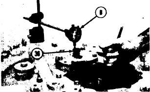
Install a 5/8”-11 NC x 6” long bolt (36) in
the directional clutch shaft and through the
hole in the cage. Make sure the head of the
bolt has a smooth surface. Install tooling
(B) as shown.
Check the end clearance of each directional
clutch by prying under the input gear with a
crowfoot bar. The end clearance must be
.002 to .006 in. (0.05 to 0.15 mm). Add or
remove shims to get correct end clearance.
Remove tooling (B) and the bolt. Install the
plugs in the cages.
2-115