TM 5-3805-263-14&P-1
NOTE
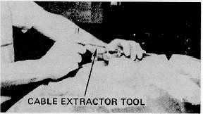
The control levers may have to be adjusted to
make the cable connections. If necessary,
use cable extractor tool 5R7047 to extend the
cables.
22.
Connect the three electrical connectors. Strap
the cables to the bar near the underside of the
upper pivot pin.
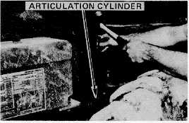
23.
Start the engine, align the articulation cylinder
eyes with the holes in the front frame and drive
in the cylinder pins on each side of the machine.
Stop the engine. Install the top and bottom caps
for each cylinder pin and tighten
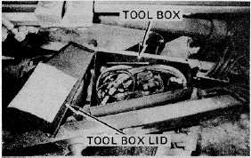
24.
store all tools, jumpers, and all other equipment in
the tool box on the draw bar and secure the lid.
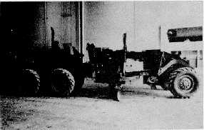
25.
Assembly is now complete, the machine is ready
for use. After approximatley one hour of operation,
check the pivot pin bolts; tighten if necessary.
WARNING
The ROPS must be installed before operating
the grader. See Volume II for installation
procedures.
112