TM5380526314&P-3
VEHICLE SYSTEMS
CIRCLE DRAWBAR BOLT
INSTALL CIRCLE DRAWBAR BOLT
Tools Needed
A
B
8S7640
Stand
1
8S7611
Tube
1
8S7615
Pin
1
8S8048
Saddle
1
5P3508
Torque Multiplier
1
1.
Put 2P2506 Thread Lubricant on the threads, nut
face and the taper of the circle drawbar bolt.
2.
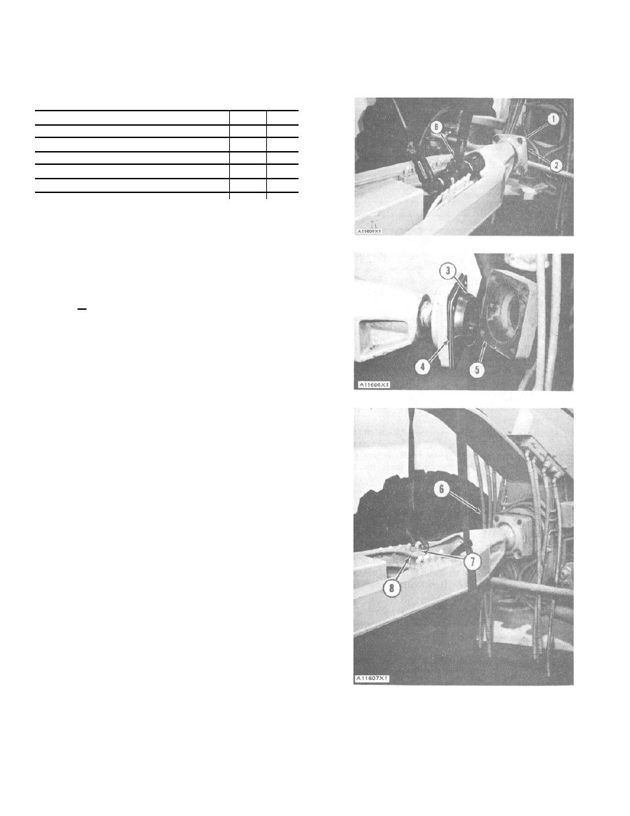
Put cap (1) in position on circle drawbar bolt
(2). Install the circle drawbar bolt in the drawbar.
3.
Install the nut on the bolt. Install tooling (B)
on the nut. Tighten the nut to a torque of 1050 + 100 lb.
ft. (1420 + 133 N.m). Bend the nut into the notch in the
circle drawbar bolt.
4.
Install bearing inserts (3) and adapter (5) on the
circle drawbar bolt. Install the bolts that hold the
adapter to the cap. Measure the distance between
the adapter and the cap with a feeler gauge.
Remove adapter (5). Install shims (4) to get the
amount of clearance measured plus .008 in.
(0.20mm). Install adapter (5) and the bolts that hold
the adapter to the cap.
5.
Fasten straps to the circle drawbar as shown. Lift
the drawbar enough to remove tooling (A) from
under the circle.
6.
Move the machine back into position over the
adapter. Use the hoist and the straps to help put the
adapter in alignment with the hole in the front
frame. Install the bolts and the lockwashers that
hold the cap and the circle drawbar bolt to the front
frame.
7.
Install the fitting in block (7). Connect oil line (8) to
the fitting.
8.
Connect oil lines (6) to their correct locations on
blocks (7).
9.
Remove the hoist and the straps.
3-215


