TM 5-3805-263-14&P-3
VEHICLE SYSTEMS
CIRCLE DRAWBAR
INSTALL CIRCLE DRAWBAR
Tools Needed
A
8S7640
Stand
1
8S7611
Tube
1
8S7615
Pin
1
8S8048
Saddle
1
1.
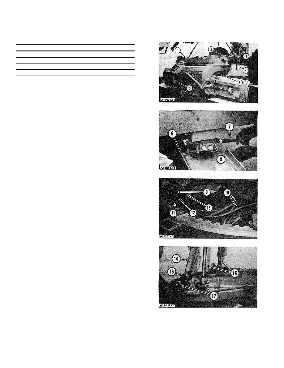
Install two 3/4"-O1NC forged eyebolts in the
drawbar. Fasten a hoist to the eyebolts and to the
circle drawbar bolt. Put circle drawbar (1) in position
in the front frame and in engagement in the circle.
2.
Install the bolts and lockwashers that hold cap (3) to
the front frame. Connect oil lines (4) to their correct
locations on blocks (2). Remove the hoist and the
eyebolts from the circle drawbar.
3.
Put guide (6) in position under the swivel joint.
Install pin (7) that holds guide (6) to swivel joint (8).
Install the cotter pin in pin (7).
4.
Connect four oil lines (10) to their correct locations
on swivel joint (8).
5.
Put shoes (12) and shims (9) in position under the
circle drawbar. Install bolts (11) and the nuts that
hold the shoes to the drawbar. Do not tighten the
nuts. Make an adjustment of the side clearance of
the side and rear shoes with the following
procedure:
a) Loosen the nuts on setscrews (13).
b) Tighten the setscrews until the shoes are
against the inside of the circle.
c) Loosen the setscrews until the circle is just free
to turn.
d) Tighten the nuts on setscrews (13).
6.
Tighten all the nuts on bolts (11) that hold the shoes
to the drawbar.
7.
Remove tooling (A) and hydraulic jack (5).
8.
Remove the strap from centershift cylinder (14).
Connect oil lines (15) to their correct locations on
centershift cylinder (14). Install the bolt that holds
the oil lines to the drawbar. Put the center-shift
cylinder and blade lift cylinders (16) in position on
the ballstuds. Install the inserts, caps (17) and the
bolts that hold the caps on the cylinders.
3-213


