TM 5-305-26314&P-3
VEHICLE SYSTEMS
CIRCLE
REMOVE CIRCLE
Tools Needed
A
8S7640
Stand
1
8S7611
Tube
1
8S7615
Pin
1
8S8040
Saddle
1
start by:
a) remove blade assembly
1.
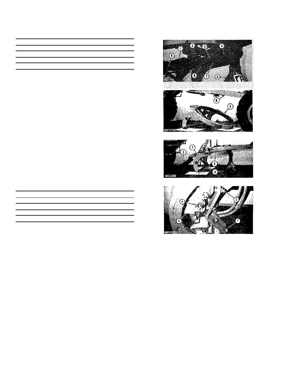
Disconnect oil lines (5) for blade tip from the swivel
joint (if so equipped). Remove the cotter pin, the
washers and pin (2) from guard assembly (1).
Remove the guard assembly (if so equipped).
2.
Put tooling (A) in position under the circle as shown.
Loosen the nuts on setscrews (3) and turn the
setscrews away from the shoes. Put identification
on shims (4) and shoes (7) as to their location on
the drawbar. Remove nuts (6) from the bolts that
hold the four shoes and the shims to the drawbar.
Remove shoes (7) and the shims.
3.
Fasten a hoist to the circle. Remove tooling (A)
from under the circle. Start the engine. Move the
machine back to remove the circle drive pinion from
engagement in the circle. Lift drawbar (8) away
from the circle. Lower circle (9) to the ground.
Remove the circle from under the machine. Weight
of the circle is 1050 lb. (473 kg).
INSTALL CIRCLE
Tools Needed
A
8S7640
Stand
1
8S7611
Tube
1
8S7615
Pin
1
8S8040
Saddle
1
1
Fasten a hoist to circle (I) and put it in position
under the machine. Install tooling (A) under the circle.
Remove the hoist. Start the engine. Put drawbar (3) in
position over the circle. Move the machine forward to put
guard assembly, the pin, washers and cotter pin position
the circle drive pinion in engagement with the circle.
under the swivel joint (if so equipped). Connect the oil
2. Put shoes (6) and the shims in their correct
lines for blade tip to the swivel joint.
locations under the drawbar. A floor jack (2) can be
end by:
in put the circle in position. Install nuts(4) and the
a) install blade assembly
washers on the bolts that hold the shoes to the
drawbar. Do not tighten nuts (4) Tighten setscrews
(5) until the shoes are against the circle. Loosen the
setscrews until the circle is just free to turn. Tighten
nuts (7).
3. Remove tooling (A) and the floor jack. Put the
3-211


