TM 53805-26314&P-3
DISASSEMBLY AND ASSEMBLY
BLADE ASSEMBLY
INSTALL BLADE ASSEMBLY
1.
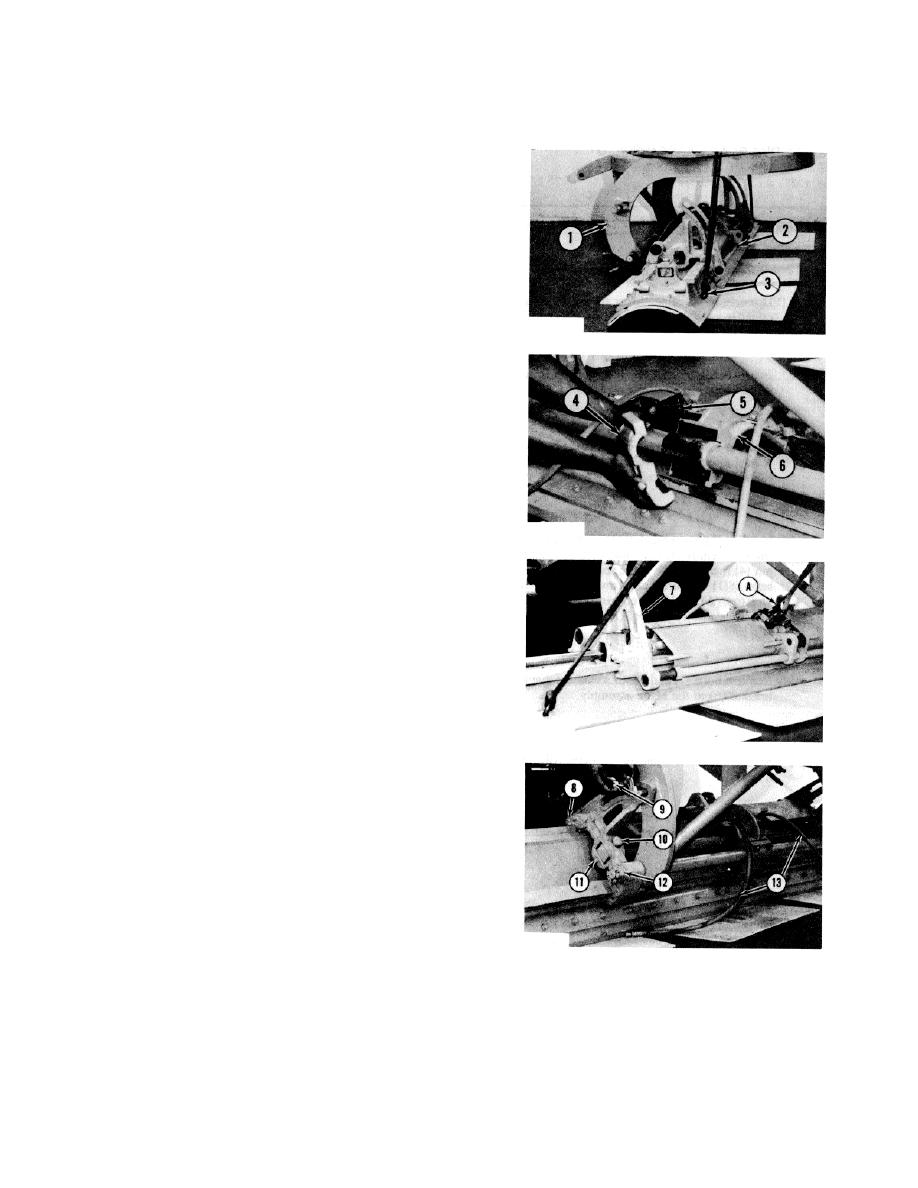
Install two 1/2"-13 NC forged eyebolts (3) in the
blade. Fasten a hoist to the eyebolts.
2.
Put the blade assembly (2) in position under the
machine as shown. Lower circle (1) into position
over the blade assembly.
3.
Put shims (5) and bracket (4) in position on the
circle bearings and bracket (6). Install the bolts and
the lockwashers that hold bracket (4) to bracket (6).
NOTE: Shims (5) must be installed between the two
brackets to get clearance between the bearings and the
brackets.
4.
Fasten tool (A) to brackets (7) and to the blade
assembly as shown.
5.
Pull brackets (7) on to the studs on the bottom of
the circle.
6.
Lift the blade with the hoist. Pull the brackets on to
the other studs with tool (A). Remove tool (A).
7.
Install the washers and nuts (8), (9) and (12). Install
the locking pins in nuts (9) and (12) on each side of
the circle.
8.
Put pin (10) in position in the bracket and the blade
sideshift cylinder. Install bolt (11) and the nut that
holds it. Connect oil lines (13) to their correct
locations on the swivel joint.
end by:
a) install blade tip cylinder
3-210


