TM 5-3805-263-14&P-3
DISASSEMBLY AND ASSEMBLY
CIRCLE DRAWBAR BOLT
REMOVE CIRCLE DRAWBAR BOLT
Tools Needed
A
B
8S7640
Stand
1
8S7611
Tube
1
8S7615
Pin
1
8S8048
Saddle
1
5P3100
Pump Group (or electric)
1
7F9540
Puller Assembly
1
1H3107
Puller Assembly
1
5F7353
Washer
2
5F7351
Nut
2
5F7343
Bearing Puller Attachment
1
1.
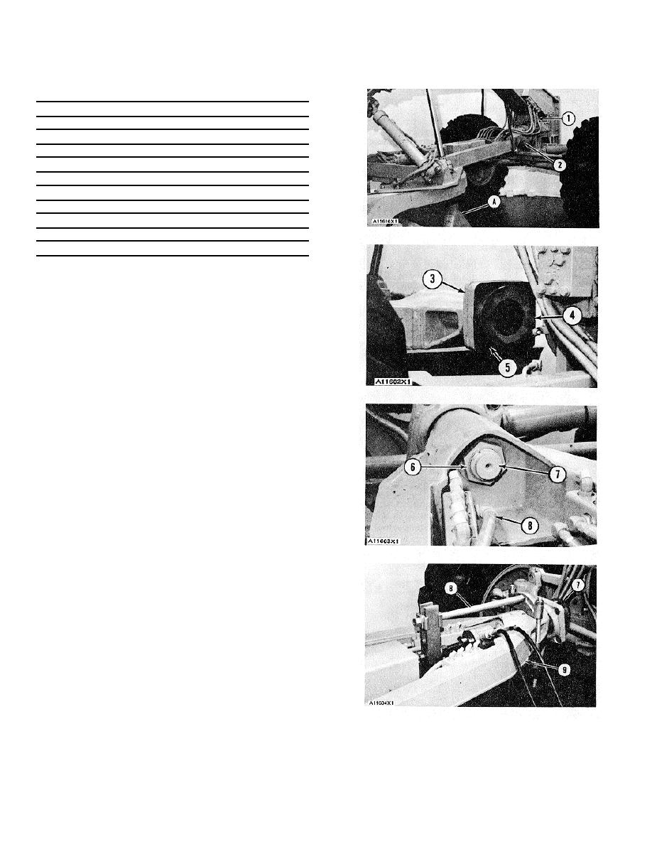
Fasten straps to the circle drawbar as shown.
Fasten a hoist to the straps.
2.
Put identification on oil lines (1) as to their locations
on the blocks on the circle drawbar. Disconnect oil
lines (1) from the blocks.
3.
Remove bolts (2) and the lockwashers that hold the
cap and the drawbar bolt to the front frame.
4.
Move the machine forward until the cap and the
drawbar bolt are free of the front frame. Lift the
circle drawbar enough to install tooling (A) under
the circle. Remove the hoist and the straps.
5.
Remove two bolts (5) that hold adapter (4) to cap
(3). Remove adapter (4), the bearing inserts and
the shims.
6.
Bend the bent part of the nut (stake) out of the
notch in circle drawbar bolt (7). Disconnect oil line
(8) from the block. Remove the fitting for oil line (8)
from the block.
7.
Loosen nut (6) until there is .25 in. (6.4 mm)
clearance between the nut and the drawbar.
8.
Install tooling (B) on the circle drawbar bolt. Loosen
bolt (7) from its taper with tooling (B).
9.
Remove tooling (B). Remove circle drawbar bolt (7)
from circle drawbar (9).
10. Remove cap (3) from the circle drawbar bolt.
3-214


