TM 53805-263-14&P-3
DISASSEMBLY AND ASSEMBLY
BLADE
REMOVE BLADE (HYDRAULIC
SIDESHIFT)
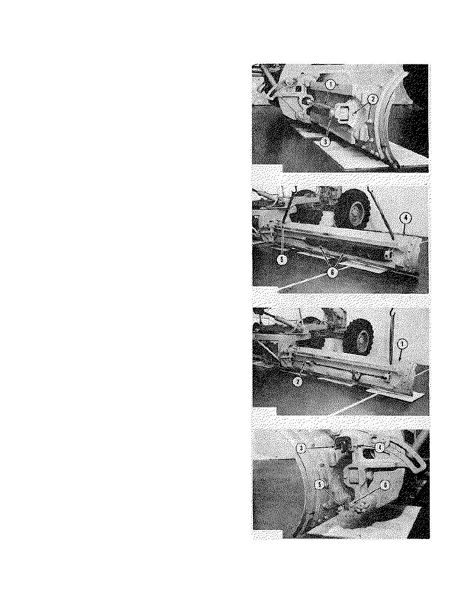
1. Move the blade as far to the right as possible. Lower
the blade until it is just off the ground.
2. Remove the bolt, washer and nut (2) that hold pin (3)
to the bracket.
3. Remove pin (3). Move cylinder rod (1) into the
cylinder as far as possible.
4. Put blocks (6) in position between the bracket and
cylinder rod (1). Push the blade away from the circle
with the cylinder rod until two 5/8"- 11 NC forged
eyebolts (5) can be installed in the blade. Fasten a
hoist to the eyebolts.
5. Remove blade (4) with the cylinder rod and the hoist.
Weight is 1500 lb. (675 kg).
6. Remove the wear plates from the circle.
INSTALL BLADE (HYDRAULIC
SIDESHIFT)
1.
Install two 5/8"-11 NC forged eyebolts in the blade.
Fasten a hoist to the eyebolts.
2. Put blade (1) in position on the circle. Fasten a
chain to the bracket and cylinder rod (2). Pull the
blade into the circle with the cylinder rod.
3. Remove the hoist and the eyebolt from the part of
the blade that is nearest the circle. Pull the blade
into the circle as far as necessary. Remove the
hoist and the chain.
4. Move the cylinder rod into position in the bracket.
Install the pin that holds the cylinder rod in the
bracket. Install the bolt, washer and the nut that
hold the pin.
5. Install the wear plates on the blade rails. Make an
adjustment to the wear plates with the following
procedure:
a) Tighten screws (4) against wear plates (3).
b) Loosen screws (4) 1/4 turn.
NOTE: Shims are under wear plates (5). Add or remove
shims to get a .005 to .035 in. (0.13 to 0.89 mm) gap
between the blade rails and the wear plates.
6.
Install plates (6) over the wear plates.
3-208


