TM 5-3805-261-34
TRANSMISSION MAINTENANCE.
14-2.
Transmission Assembly.
DISASSEMBLY
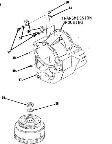
50. Remove two dowel pins (47 and 48)
and plug (49, Figure 14-14) from
transmission housing.
51. Remove breather (50) and elbow
(51).
52. Remove two bolts (52), lock-
washers (53) and lifting eyes
(54).
NOTE
The following is a mainte-
nance procedure for the
disassembly of the forward
directional clutch. The
maintenance procedure for the
disassembly of the reverse
directional clutch is
identical.
53. Bend nut lock (56) away from lock
nut (55, Figure 14-15).
54. Using a spanner socket, remove
lock nut (55) and nut lock (56).
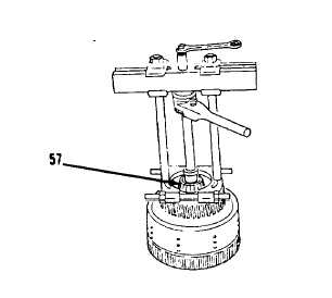
55. Using puller assembly, ratchet
box wrench, bearing pulling
attachment and spacer, remove
roller bearing (57, Figure
14-16).
Go to Sheet 10
14-11
Figure 14-14.
Figure 14-15.
Figure 14-16.


