TM 5-3805-261-34
TRANSMISSION MAINTENANCE.
14-2.
Transmission Assembly. (Sheet 7 of 20)
DISASSEMBLY
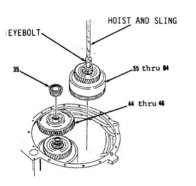
34. Lift up and push down on items 44
thru 46 as an assembly to free
roller bearing (35, Figure 14-9).
35. Remove roller bearing (35).
NOTE
The following is a mainte-
nance procedure for the
removal of the forward
directional clutch. The
maintenance procedure for the
reverse directional clutch is
identical.
36. Install 3/4-10NC forged eyebolt
in items 55 thru 84 as an
assembly.
WARNING
Weight of each directional
clutch is approximately 80
lbs. Use adequate hoist and
sling for lifting. Failure
to follow this procedure may
cause INJURY. If you are
injured, seek medical aid
immediately.
37. Attach hoist and sling to
3/4-10NC forged eyebolt.
38. Lift up on items 44 thru 46 as an
assembly to allow removal of
items 55 thru 84 as an assembly.
39. Remove items 55 thru 84 as an
assembly and place on workbench
to be disassembled later.
40. Remove hoist and sling.
41. Remove 3/4-10NC forged eyebolt.
Go to Sheet 8
14-9
Figure 14-9.