TM 5-3805-261-34
CHARGING SYSTEM MAINTENANCE.
4-5.
Alternator (Bosch). (Sheet 5 of 12)
DISASSEMBLY
22. Remove field coil (24) from inner frame (27).
Remove all epoxy putty from inner frame (27)
groove.
23. Remove ring (25) and bearing (26).
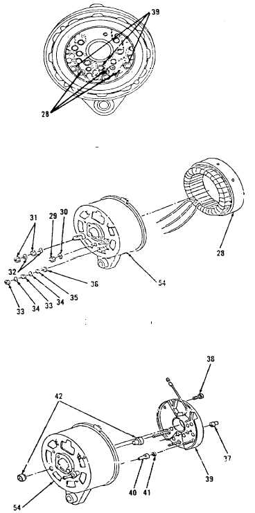
24. Unsolder three stator (28) wires from three diode
assembly (39, Figure 4-25) terminals.
25. Using two screwdrivers, pry apart stator (28) and
remove from frame (54, Figure 4-26). Be careful
not to damage stator (28).
NOTE
Testing of diode assembly is necessary prior to
further disassembly.
26. Remove diode assembly (39). Refer to Testing,
step 10.
27. Remove nut (29) and lockwasher (30) from
frame (54).
28. Remove two nuts (31) and lockwashers (32).
29. Remove two nuts (33), lockwashers (34), washer
(35) and insulator (36).
30. Heat sleeve (37) with soldering iron while
gripping edge of sleeve (37, Figure 4-27) with
needle nose pliers.
31. Unsolder and remove sleeve (37).
Figure 4-25.
Figure 4-26.
Figure 4-27.
Go to Sheet 6
4-27