TM 5-3805-261-34
CHARGING SYSTEM MAINTENANCE.
4-5.
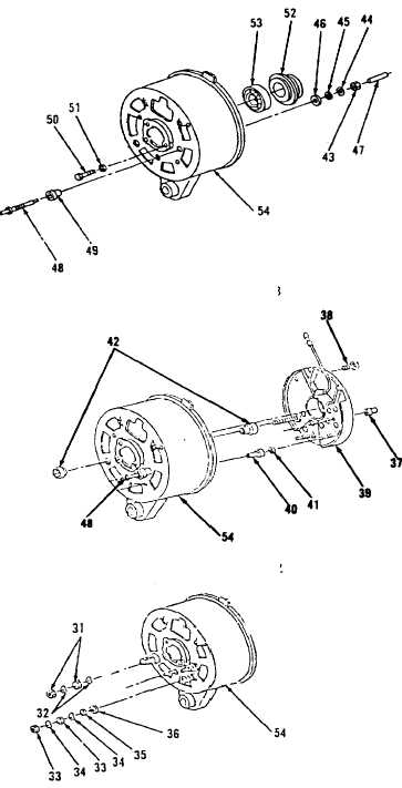
Alternator (Bosch). (Sheet 9 of 12)
ASSEMBLY
1.
Install bearing (53) in frame
(54, Figure 4-28). Apply bearing
grease, if necessary.
2.
Position ring (52) over bearing
(53).
3.
Install three lockwashers (51)
and screws (50).
4.
Install bushing (49), pin
terminal (48), insulators (47 and
46), washer (45), lockwasher (44)
and nut (43) in hole of frame
(54) marked "R".
5.
Position two bushings (42) in
hole of frame (54, Figure 4-32)
marked “B+".
6.
Position washer (41) and
insulator (40) in hole of frame
(54) marked "D+".
7.
Install diode assembly (39) in
frame (54).
8.
Install two screws (38) securing
diode assembly (39) to frame
(54).
9.
Position sleeve (37) on end of
pin terminal (48) and solder.
10. Install insulator (36), washer
(35), two lockwashers (34) and
nuts (33, Figure 4-26) on
terminal stud marked "B+".
11. Install two lockwashers (32) and
nuts (31) on terminal stud marked
"B+".
Go to Sheet 12
4-31
Figure 4-28.
Figure 4-32.
Figure 4-31.