TM 5-3805-261-34
FUEL SYSTEM MAINTENANCE. (cont)
3-27.
Governor and Fuel Injection Pump. (Sheet 6 of 9)
STATIC FUEL ADJUSTMENT (cont)
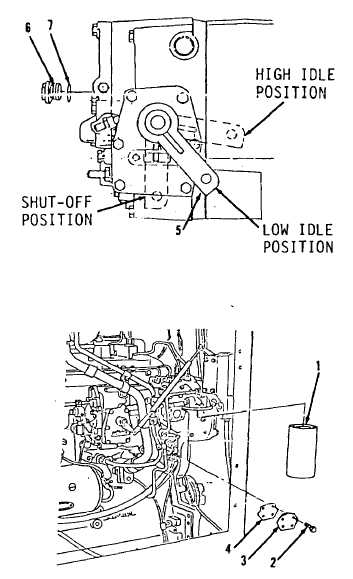
25. Remove bolt from plug (6, Figure
3-104) hole and install into end
of compressor.
26. Install new preformed packing (7)
and plug (6).
27. Install new gasket (4), cover (3)
and four bolts (2, Figure 3-99)
to right side of fuel injection
pump.
GOVERNOR ADJUSTMENT
WARNING
If fuel injection pump and
governor were assembled
wrong, it is possible for the
engine to run out of control.
Follow the next step to take
the necessary precaution to
stop the engine if it
overspeeds.
1.
Remove turbocharger air pipe from
top of engine. Refer to TM 5-
3805-261-20. If engine runs out
of control, a steel plate can be
put over the turbocharger air
inlet to starve engine of air.
2.
Install secondary fuel filter (1)
to right side of fuel injection
pump.
3.
Install tachometer drive to rear
of fuel injection pump. Refer to
paragraph 3-20.
Go to Sheet 7
3-140
Figure 3-104.
Figure 3-99.