TM 5-3805-261-23-1
SUPPLEMENTAL STEERING HYDRAULIC PRESSURE SWITCH REPLACEMENT - CONTINUED
0087 00
REMOVAL
1.
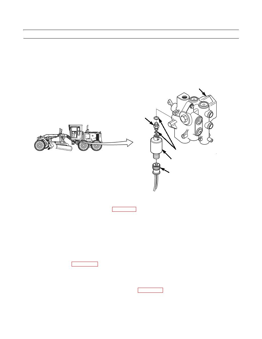
Disconnect connector assembly (5) from switch (4) under left side of cab.
2.
Remove switch (4).
3.
Remove adapter (1) and two preformed packings (3) from combination valve (2). Discard preformed packings.
2
1
3
4
5
397-265
CLEANING AND INSPECTION
Clean and inspect all parts in accordance with WP 0021 00.
INSTALLATION
1.
Install two new preformed packings (3) on adapter (1).
2.
Install adapter (1) on combination valve (2).
3.
Install switch (4).
4.
Install connector assembly (5) to switch (4).
5.
Connect battery cables (WP 0125 00).
6.
Turn battery disconnect switch to ON position and start engine (TM 5-3805-261-10).
7.
Check for leaks. Stop engine.
8.
Check hydraulic fluid level. Refill hydraulic tank as required (WP 0216 00).
END OF WORK PACKAGE
0087 00-2


