TM 5-3805-261-23-1
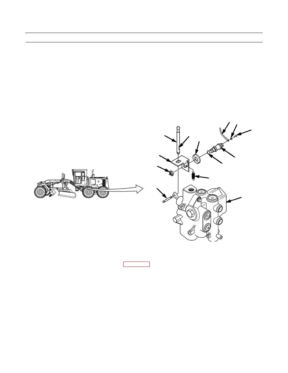
SUPPLEMENTAL STEERING PUMP VALVE SWITCH MAINTENANCE - CONTINUED
0086 00
REMOVAL
NOTE
Tag wire assemblies before disconnecting to aid in installation.
1.
Remove two screws (4) and washers (3) and disconnect two wire assemblies (2) from switch (5).
2.
Remove nut (10), switch (5), and retainer (1) from bracket (11).
3.
Remove pin (9) and clevis (12). Discard pin.
4.
Remove spring (7) and bracket (11) from combination valve (8).
2 3
4
12
13
1
11
5
10
6
7
9
8
397-264
CLEANING AND INSPECTION
Clean and inspect all parts in accordance with WP 0021 00.
INSTALLATION/ADJUSTMENT
NOTE
Do not tighten nut.
1.
Install retainer (1), switch (5), and nut (10) on bracket (11).
1.
Move switch (5) up or down to locate roller (6) in lower half of slot (13) in clevis (12).
2.
Tighten nut (10) finger-tight.
3.
Move bracket (11) to lightly touch lower half of slot (13) in clevis (12).
4.
Tighten nut (10) to 15 lb-ft (20 Nm).
0086 00-2


