TM 5-3805-261-20
HYDRAULIC SYSTEM MAINTENANCE.
15-31.
Scarifier Lines, Fittings and Hoses. (Sheet 5 of 5)
INSTALLATION
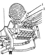
10.
Install two new preformed packings (2)
and connectors (1, Figure 15-151) on right
hand control valve; first valve assembly on
outside of right side front cab.
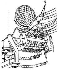
11.
Connect two hose assemblies (5, Figure
15-150).
WARNING
Only
a
qualified
operator
may
perform the next procedure. All other
personnel must clear the immediate
area. Failure to follow this procedure
may cause INJURY. If you are
injured,
seek
medical
aid
immediately.
12.
Start engine. Refer to TM 53805-261-10.
13.
Operate scarifier control. Move system
through at least five full movements of
travel to bleed air from system.
14.
Stop engine.
15.
Inspect hose assemblies and connections
for leaks.
16.
Refill hydraulic tank to proper level. Refer
to LO 5-3805-261-12.
NOTE
Return
130G
Grader
to
original
equipment condition.
Figure 15-151.
Figure 15-150.
End of Task
15-175