
TM 5-3805-293-23-5
0323
INSTALLATION CONTINUED
000323
WARN I N G
Use extreme caution when handling heavy parts. Provide adequate support and use
assistance during procedure. Ensure that any lifting device used is in good condition and
of suitable load capacity. Keep clear of heavy parts supported only by lifting device.
Failure to follow this warning may result in injury or death to personnel.
N OT E
Lift arm assembly weighs approximately 400 lb (180 kg).
Reposition sling and lifting device asrequired to install lift arm assembly.
10. Install sling and lifting device on lift arm assembly.
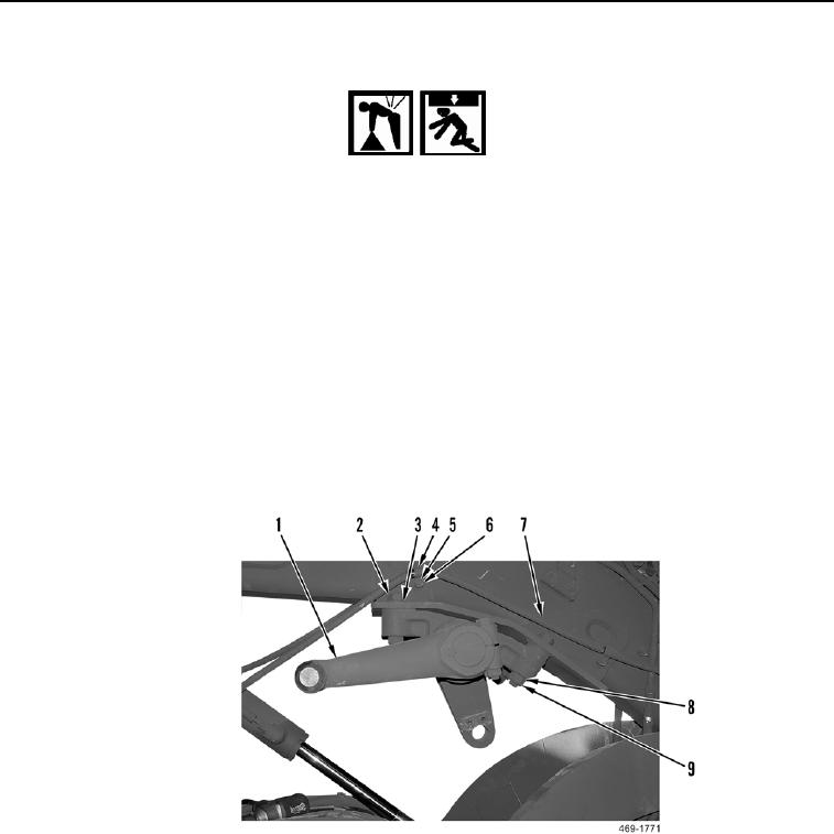
11. Using lifting device, install lift arm assembly (Figure 7, Item 1) on machine.
12. Install four washers (Figure 7, Item 3), bolts (Figure 7, Item 2), washers (Figure 7, Item 8), and new locknuts
(Figure 7, Item 9) on lift arm assembly (Figure 7, Item 1). Torque to 664 74 lb-ft (900 100 Nm).
13. Reposition hose (Figure 7, Item 7) and install two clamps (Figure 7, Item 4), washers (Figure 7, Item 5), and
bolts (Figure 7, Item 6) on machine.
Figure 7. Lift Arm.
0323