
TM 5-3805-293-23-5
0323
INSTALLATION CONTINUED
N OT E
Installation is the same for left and right link assembly. Procedure shown is for left link
assembly.
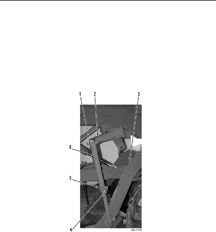
14. Install link assembly (Figure 8, Item 1) on lift arm (Figure 8, Item 2) and drawbar (Figure 8, Item 3).
N OT E
Install pin on link assembly as noted during removal.
15. Install lock pin (Figure 8, Item 6) on link assembly (Figure 8, Item 1).
16. Tighten bolt (Figure 8, Item 5) and nut (Figure 8, Item 4) on link assembly (Figure 8, Item 1).
Figure 8. Link Assembly.
0323