
TM 5-3805-293-23-5
0323
REMOVAL CONTINUED
N OT E
Note location of pin prior to removal to aid in installation.
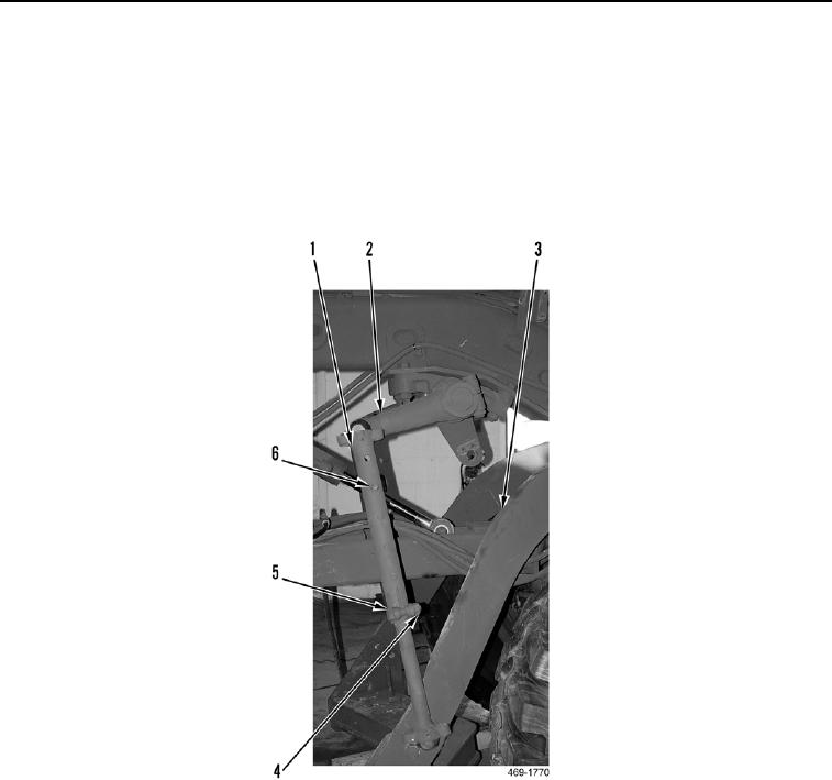
3. Loosen bolt (Figure 3, Item 5) and nut (Figure 3, Item 4) on link assembly (Figure 3, Item 1).
4. Remove lock pin (Figure 3, Item 6) from link assembly (Figure 3, Item 1)
5. Remove link assembly (Figure 3, Item 1) from lift arm (Figure 3, Item 2) and drawbar (Figure 3, Item 3).
Figure 3. Link Assembly.
0323