
TM 5-3805-293-23-5
0286
INSTALLATION CONTINUED
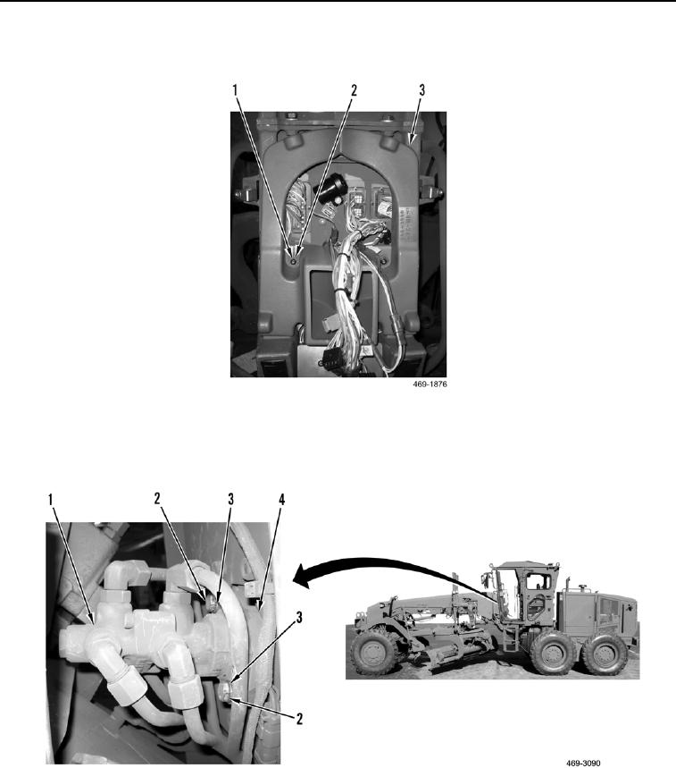
4. Install upper duct (Figure 6, Item 3), two washers (Figure 6, Item 2), and screws (Figure 6, Item 1) on cab.
Figure 6. Upper HVAC Duct.
0286
5. Install two washers (Figure 7, Item 3) and bolts (Figure 7, Item 2) on brake control valve (Figure 7, Item 1) and
service brake control (Figure 7, Item 4).
Figure 7. Brake Control Valve.
0286
END OF TASK