• Home
  • Download PDF
  • Order CD-ROM
  • Order in Print
Figure 1. Brake Control Valve.
Figure 4. Brake Pedal Assembly.

Maintenance Manual For Motorized Road Grader Model 120M - 5 Page Navigation
  134    135    136    137    138  139  140    141    142    143    144  
img
.
TM 5-3805-293-23-5
0286
REMOVAL CONTINUED
2. Remove two screws (Figure 2, Item 1), washers (Figure 2, Item 2), and upper duct (Figure 2, Item 3) from cab.
Figure 2. Upper HVAC Duct.
0286
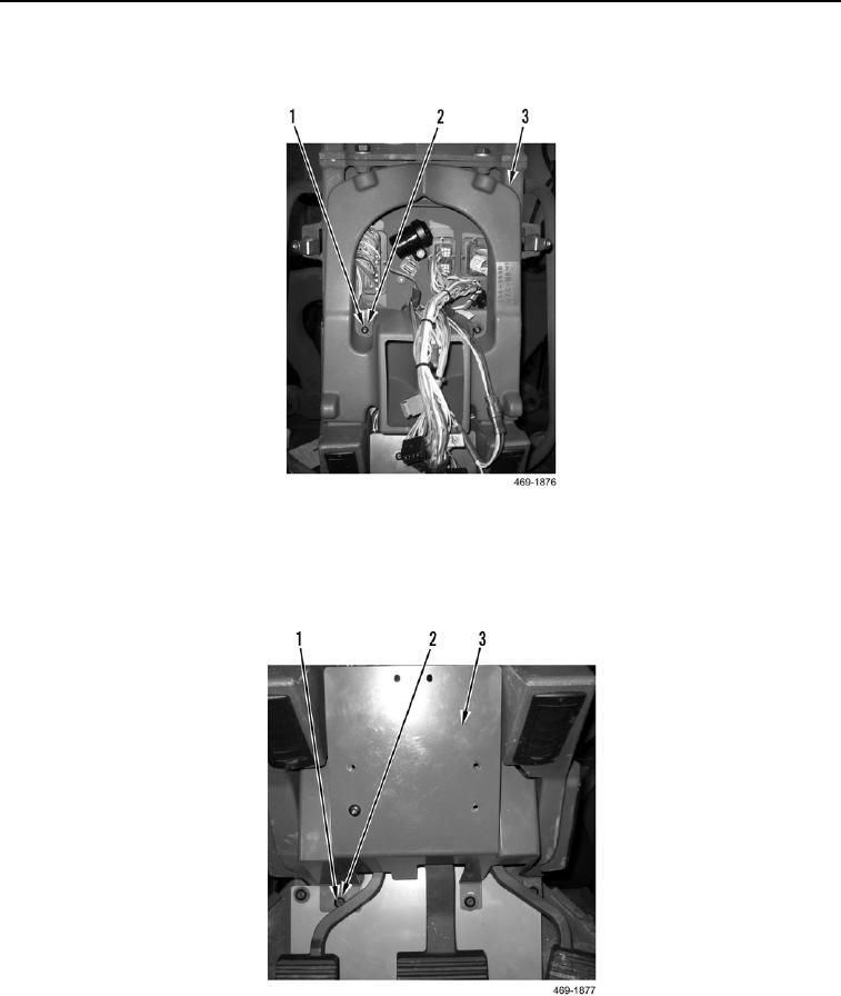
3. Remove three screws (Figure 3, Item 1), washers (Figure 3, Item 2), and service brake control cover (Figure 3,
Item 3) from cab.
Figure 3. Service Brake Control Cover.
0286
0286-3


Privacy Statement
Press Release
Contact

© Copyright Integrated Publishing, Inc.. All Rights Reserved.