
TM 5-3805-293-23-5
0286
INSTALLATION
000286
N OT E
Install wires as tagged during removal.
1. Install brake pedal assembly (Figure 4, Item 5), three washers (Figure 4, Item 4), and bolts (Figure 4, Item 3)
on cab.
2. Connect five pigtail connectors (Figure 4, Item 1) on cab lower wiring harness (Figure 4, Item 2).
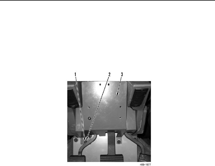
3. Install service brake control cover (Figure 5, Item 3), three washers (Figure 5, Item 2), and screws (Figure 5,
Item 1) on cab.
Figure 5. Service Brake Control Cover.
0286