
TM 5-3805-293-23-5
0287
DISASSEMBLY
000287
N OT E
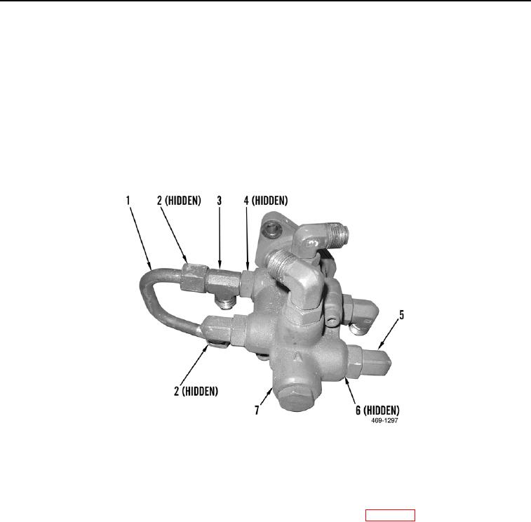
Note direction and location of elbows and tee fitting to aid in installation.
1. Remove pipe (Figure 3, Item 1) and two O-rings (Figure 3, Item 2) from brake control valve (Figure 3, Item 7).
Discard O-rings.
2. Remove five elbows (Figure 3, Item 5) and O-rings (Figure 3, Item 6) from brake control valve (Figure 3,
Item 7). Discard O-rings.
3. Remove tee fitting (Figure 3, Item 3) and O-ring (Figure 3, Item 4) from brake control valve (Figure 3, Item 7).
Discard O-ring.
Figure 3. Brake Control Valve Disassembly.
0287
END OF TASK
CLEANING AND INSPECTION
000287
Clean and inspect all parts IAW Mechanical General Maintenance Instructions (WP 0346).
END OF TASK