
TM 5-3805-293-23-5
0282
DISASSEMBLY CONTINUED
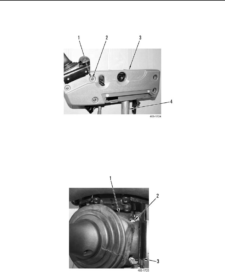
3. Remove five screws (Figure 9, Item 1), washers (Figure 9, Item 2), and outer panel cover (Figure 9, Item 3)
from joystick support (Figure 9, Item 4).
Figure 9. Outer Panel Cover.
0282
N OT E
Joystick control screws are located under rubber boot.
4. Remove four screws (Figure 10, Item 2) and joystick control (Figure 10, Item 1) from joystick control bracket
(Figure 10, Item 3).
Figure 10. Joystick Control.
0282