
TM 5-3805-293-23-5
0282
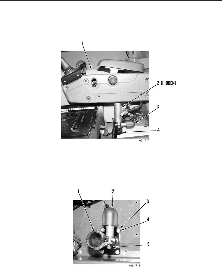
REMOVAL CONTINUED
8. Loosen joystick support height adjustment locking knob (Figure 5, Item 3).
9. Remove joystick support (Figure 5, Item 1) and spring (Figure 5, Item 2) from mount (Figure 5, Item 4).
10. Set joystick support (Figure 5, Item 1) on a suitable work surface.
Figure 5. Upper Joystick Mounting Tube.
0282
11. Remove four bolts (Figure 6, Item 4), washers (Figure 6, Item 3), and joystick support mount (Figure 6, Item 1)
from machine.
12. Remove locknut (Figure 6, Item 5) and lock knob (Figure 6, Item 2) from joystick support mount (Figure 6,
Item 1). Discard locknut.
Figure 6. Lower Joystick Mounting Tube.
0282
END OF TASK