
TM 5-3805-293-23-5
0282
CLEANING AND INSPECTION
000282
1. Clean and inspect all parts IAW Mechanical General Maintenance Instructions (WP 0346).
2. Clean and inspect all electrical parts IAW Electrical General Maintenance Instructions (WP 0347).
END OF TASK
ASSEMBLY
000282
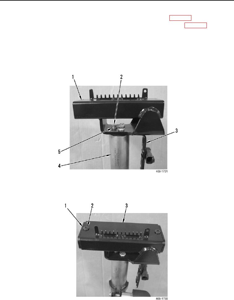
1. Install plate (Figure 18, Item 3), joystick support (Figure 18, Item 1), washers (Figure 18, Item 5), and three
bolts (Figure 18, Item 2) on upper joystick support mount tube (Figure 18, Item 4).
Figure 18. Joystick Support and Plate.
0282
2. Install two bushings (Figure 19, Item 1) and screws (Figure 19, Item 2) on joystick support (Figure 19, Item 3).
Figure 19. Slide Lock Frame Bushings.
0282