
TM 5-3805-293-23-5
0282
DISASSEMBLY CONTINUED
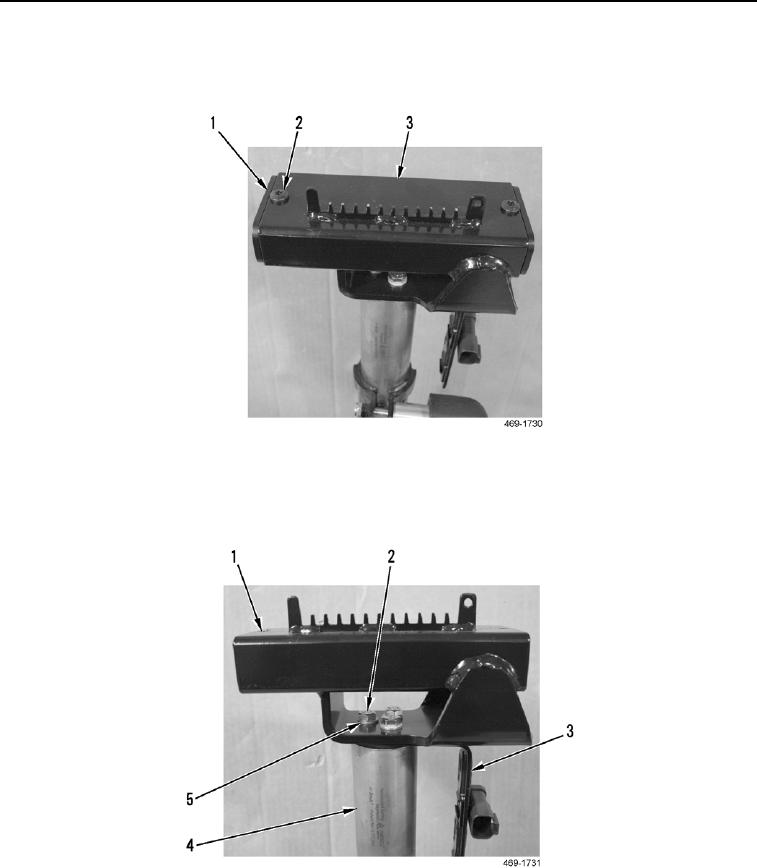
13. Remove two screws (Figure 16, Item 2) and bushings (Figure 16, Item 1) from joystick support (Figure 16,
Item 3).
Figure 16. Slide Lock Frame Bushings.
0282
14. Remove three bolts (Figure 17, Item 2), washers (Figure 17, Item 5), joystick support (Figure 17, Item 1), and
plate (Figure 17, Item 3) from upper joystick support mount tube (Figure 17, Item 4).
Figure 17. Joystick Support and Plate.
0282
END OF TASK