
TM 5-3805-293-23-4
0245
INSTALLATION CONTINUED
N OT E
Install wires as tagged during removal.
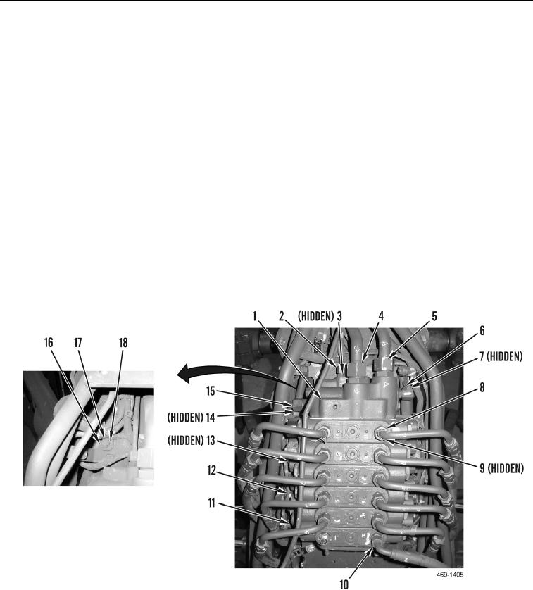
11. Install washer (Figure 16, Item 17) and bolt (Figure 16, Item 16) on pipe cover plate (Figure 16, Item 18).
12. Connect 12 harness connectors (Figure 16, Item 13) to front valve bank (Figure 16, Item 1).
13. Install 10 new tiedown straps (Figure 16, Item 11) on harness (Figure 16, Item 12).
14. Install pilot/shutoff pressure line (Figure 16, Item 5) on front valve bank (Figure 16, Item 1).
15. Install pump pressure line (Figure 16, Item 4) on front valve bank (Figure 16, Item 1).
16. Install new O-ring (Figure 16, Item 3) and pilot/load sense line (Figure 16, Item 2) on front valve bank
(Figure 16, Item 1).
17. Install new O-ring (Figure 16, Item 7) and left return line (Figure 16, Item 6) on front valve bank (Figure 16,
Item 1).
18. Install new O-ring (Figure 16, Item 14) and right return line (Figure 16, Item 15) on front valve bank (Figure 16,
Item 1).
19. Install 11 new O-rings (Figure 16, Item 9), 10 implement control lines (Figure 16, Item 8), and implement
control hose (Figure 16, Item 10) on front valve bank (Figure 16, Item 1).
Figure 16. Hydraulic Lines.
0245
Change 1

