
TM 5-3805-293-23-3
0159
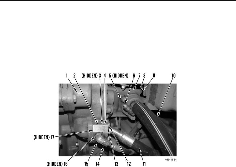
INSTALLATION CONTINUED
4. Install new O-ring (Figure 4, Item 17), spacer (Figure 4, Item 2), new O-ring (Figure 4, Item 3), hose
(Figure 4, Item 11), two clamps (Figure 4, Item 4), four washers (Figure 4, Item 13), and bolts (Figure 4,
Item 12) on charging pump (Figure 4, Item 1).
5. Install two new O-rings (Figure 4, Item 16) and elbow (Figure 4, Item 15) on charging pump (Figure 4, Item 1).
Connect hose (Figure 4, Item 14) to elbow.
6. Install new O-ring (Figure 4, Item 5), screen assembly (Figure 4, Item 7), three washers (Figure 4, Item 8), and
bolts (Figure 4, Item 9) on charging pump (Figure 4, Item 1). Torque bolts to 41 lb-ft (55 Nm).
7. Connect hose (Figure 4, Item 10) and install clamp (Figure 4, Item 6) on screen assembly (Figure 4, Item 7).
Figure 4. Charging Pump Hoses.
0159