
TM 5-3805-293-23-3
0160
REMOVAL
000160
N OT E
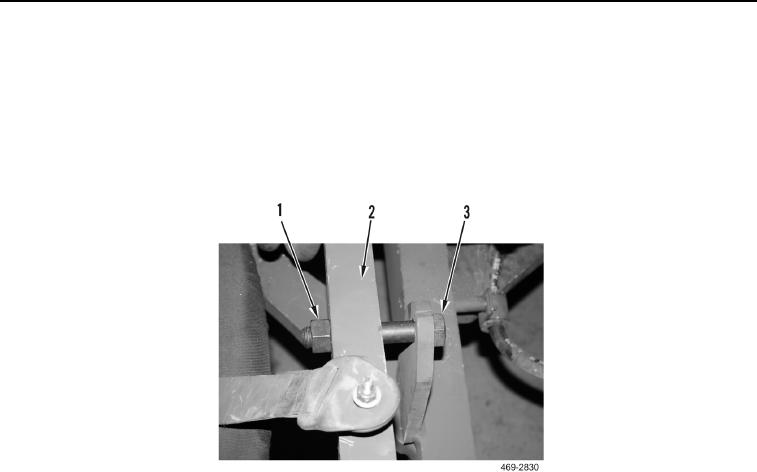
Wheel lean lock bolt is installed on the left side of the front axle.
1. Install wheel lean lock bolt (Figure 1, Item 3) and nut (Figure 1, Item 1) on front axle (Figure 1, Item 2). Hand
tighten only.
Figure 1. Wheel Lean Lock Bolt.
0160
2. Attach sling and lifting device to wheel lean arm.
3. Remove bolt (Figure 2, Item 4), washer (Figure 2, Item 3), retainer (Figure 2, Item 2), and pin (Figure 2, Item 5)
from wheel lean arm (Figure 2, Item 10). Position wheel lean cylinder (Figure 2, Item 1) aside.
4. Remove bolt (Figure 2, Item 6), washer (Figure 2, Item 7), spacer (Figure 2, Item 8), and pin (Figure 2, Item 9)
from wheel lean arm (Figure 2, Item 10).