
TM 5-3805-293-23-3
0103
INSTALLATION
Valve Mechanism Cover Base
000103
N OT E
Ensure gasket is seated correctly in the groove in the machined face of valve mechanism
cover base.
1. Install new gasket (Figure 3, Item 3) on valve mechanism cover base (Figure 3, Item 2).
2. Install 14 bolts (Figure 3, Item 1) and valve mechanism cover base (Figure 3, Item 2) on cylinder head. Tighten
bolts in sequence shown (Figure 4) to 79 lb-in. (9 Nm).
3. Install fuel injector wiring harness. Refer to procedure in this work package.
Fuel Injector Wiring Harness
000103
N OT E
Install wires as tagged during removal.
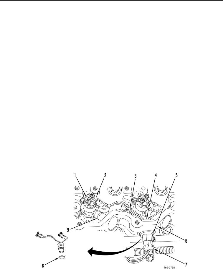
1. Lubricate three new O-rings (Figure 5, Item 8) with O-ring assembly compound. Install three fuel injector har-
ness connectors (Figure 5, Item 4) and O-rings on valve mechanism cover base (Figure 5, Item 6).
2. Install three snaprings (Figure 5, Item 5) on fuel injector harness connectors (Figure 5, Item 4) and connect fuel
wiring harness plugs (Figure 5, Item 7).
3. Install three new clips (Figure 5, Item 3) on valve cover base (Figure 5, Item 6).
4. Install 12 fuel injector harness connections and nuts (Figure 5, Item 2) on six fuel injectors (Figure 5, Item 1).
Torque to 21 lb-in. (2.4 Nm).
5. Install six sleeves (Figure 5, Item 9) on valve cover base (Figure 5, Item 6).
6. Install valve mechanism cover. Refer to procedure in this work package.
Figure 5. Fuel Injector Harness.
0103
Change 1