
TM 5-3805-293-23-3
0102
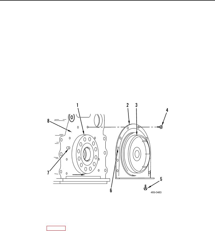
INSTALLATION CONTINUED
1. Place crankshaft rear seal assembly (Figure 2 Item 2) over crankshaft flange (Figure 2, Item 1) and align dowel
(Figure 2, Item 7) with alignment hole (Figure 2, Item 6) in crankshaft rear seal assembly.
2. Ensure plastic sleeve (Figure 2, Item 3) is engaged on crankshaft flange (Figure 2, Item 1). Push rear seal
assembly (Figure 2, Item 2) squarely onto crankshaft flange and seat seal against cylinder block (Figure 2,
Item 8). Plastic sleeve will be forced out of seal. Discard sleeve.
3. Install two screws (Figure 2, Item 5) in outer holes of crankshaft rear seal assembly (Figure 2, Item 2). Tighten
screws to 11 lb-ft (15 Nm).
4. Install two screws (Figure 2, Item 4) in upper holes of crankshaft rear seal assembly (Figure 2, Item 2). Tighten
screws to 16 lb-ft (22 Nm).
5. Unscrew two screws (Figure 2, Item 5) one complete turn.
6. Install remaining six screws (Figure 2, Item 4) in crankshaft rear seal assembly (Figure 2, Item 2). Tighten all
eight screws to 16 lb-ft (22 Nm).
7. Install remaining two screws (Figure 2, Item 5) in crankshaft rear seal assembly (Figure 2, Item 2). Tighten all
four screws to 16 lb-ft (22 Nm).
.
Figure 2. Crankshaft Rear Seal Assembly.
0102
END OF TASK
FOLLOW-ON TASKS
000102
Install flywheel housing (WP 0101).
END OF TASK
END OF WORK PACKAGE