TM 5-3805-293-23-3
0103
INSTALLATION CONTINUED
Valve Mechanism Cover
000103
N OT E
Ensure harness assemblies are not in contact with the rocker arms or pinched by the valve
mechanism cover.
Ensure the gasket is fully seated intothe groove of the valve mechanism cover.
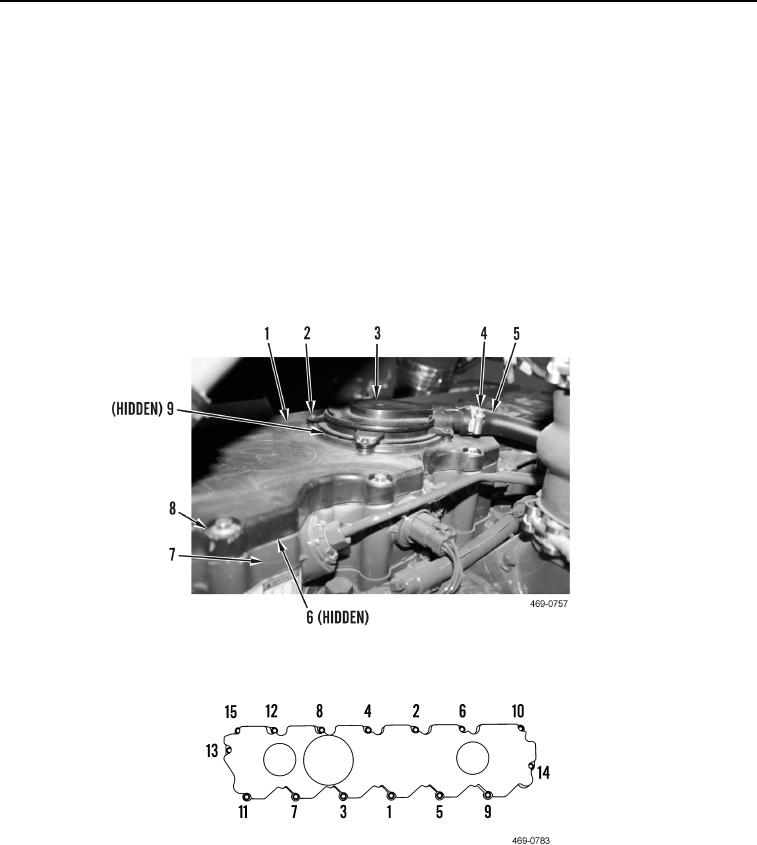
1. Install new gasket (Figure 6, Item 6), valve mechanism cover (Figure 6, Item 1), and 15 bolts (Figure 6, Item 8)
on valve mechanism cover base (Figure 6, Item 7). Tighten bolts in sequence shown (Figure 7) to 79 lb-in.
(9 Nm).
2. Install new O-ring (Figure 6, Item 9), breather (Figure 6, Item 3), and four screws (Figure 6, Item 2) on valve
mechanism cover (Figure 6, Item 1).
3. Connect breather hose (Figure 6, Item 5) to breather (Figure 6, Item 3) and tighten clamp (Figure 6, Item 4).
Figure 6. Valve Mechanism Cover.
0103
Figure 7. Valve Mechanism Cover Torque Sequence.
0103
END OF TASK
Change 1

