
TM 5-3805-293-23-3
0044
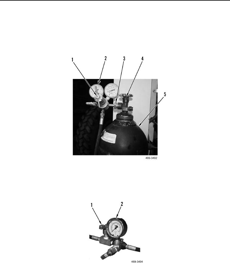
BRAKE ACCUMULATOR SERVICE TEST AND CHARGE CONTINUED
20. Connect regulator nut (Figure 53, Item 3) to nitrogen release valve (Figure 53, Item 4).
21. Turn regulating valve (Figure 53, Item 1) counterclockwise (Figure 53, Item 5) until screw tension is released.
22. Open valve (Figure 53, Item 4) on nitrogen cylinder (Figure 53, Item 5).
23. Turn regulating valve (Figure 53, Item 1) clockwise until pressure on left pressure gauge (Figure 53, Item 2)
indicates pressure specified in Table 1.
Figure 53. Regulator and Nitrogen Bottle.
0044
24. Open valve (Figure 54, Item 1) on valve assembly to charge accumulator.
25. Close valve (Figure 54, Item 1) on valve assembly when pressure gauge (Figure 54, Item 2) indicates pressure
specified in Table 1.
Figure 54. Pressure Gauges and Regulating Valves.
0044