
TM 5-3805-293-23-3
0044
BRAKE ACCUMULATOR SERVICE TEST AND CHARGE CONTINUED
N OT E
Use thread sealant on all threaded connections.
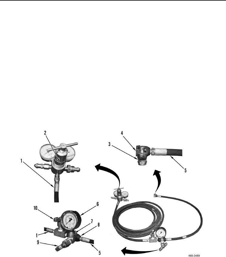
3. Connect long hose (Figure 49, Item 1) to regulator (Figure 49, Item 2).
4. Connect valve (Figure 49, Item 3) to elbow (Figure 49, Item 4).
5. Connect short hose (Figure 49, Item 5) to elbow (Figure 49, Item 4).
6. Connect valve (Figure 49, Item 9) to tee (Figure 49, Item 8).
7. Connect adapter (Figure 49, Item 7) to valve (Figure 49, Item 9).
8. Connect pressure gauge (Figure 49, Item 6) to adapter (Figure 49, Item 7).
9. Connect valve (Figure 49, Item 10) to tee (Figure 49, Item 8).
10. Connect long hose (Figure 49, Item 1) to valve (Figure 49, Item 10).
11. Connect short hose (Figure 49, Item 5) to tee (Figure 49, Item 8).
12. Close valves (Figure 49, Item 2) and (Figure 49, Item 10) by turning clockwise.
13. Open valve (Figure 49, Item 9) by turning counterclockwise.
14. Close valve (Figure 49, Item 3) by turning counterclockwise.
Figure 49. Nitrogen Charging Kit Assembly.
0044