ELECTRICAL SYSTEM
TM 5-3805-263-14&P-2
TESTING AND ADJUSTING
1. To adjust the pinion distance, connect the solen-
oid to a 12 volt battery as shown.
Momentarily flash the jumper lead from the mo-
tor terminal stud of the solenoid to the terminal stud
at (1) in the commutator end head to shift the solen-
oid and drive into the cranking position.
Remove the jumper lead.
NOTE: The drive will remain in the cranking posi-
tion until the battery is disconnected.
Push the drive toward the commutator end of the
motor to eliminate any slack movement in the link-
age and measure the distance between the outside
edge of the drive sleeve and the thrust washer. The
distance (3) must he .02 to .05 in. (0.51 to 1.27 mm).
Adjust to this dimension by turning the adjusting
nut (2) in or out as required.
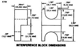
2. To test assembly of solenoid, it will be necessary
to have an interference block cut to the dimen-
sions shown.
Connect the solenoid to 24 volts as shown.
Position the .9844 in. (25.003 mm) side of the
interference block against the pinion as shown and
close the switch in the battery circuit,
With the switch closed and the .9844 in. (25.003
mm) side of the interference block in place, the test
light must not light. Make sure the interference
block is against the drive gear and not against the
drive sleeve.
CAUTION
Due to the amount of current being passed
through the solenoid series winding, these
tests should be made as brief as possible.
If the test light lights, the solenoid has been assem-
bled wrong. Remove the cover from the solenoid and
check the contact component assembly. If the test
light does not light. connect a carbon pile between
the switch and battery and voltmeter to the terminals
(4) and (5).
1-78


