ELECTRICAL SYSTEM
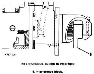
Position the .50 in. (12.7 mm) side of the interfer-
ence block against the drive gear and adjust the
voltage with the carbon pile. The test light must light
before 16 volt reading. If the test light does not light,
turn the adjusting nut (2) out until the light comes
on. After all adjustments have been made, replace
the plug and washer in the shift linkage cover.
P i n i o n C l e a r a n c e A d j u s t m e n t ( D e l c o - R e m y )
Whenever the solenoid is installed, the pinion
clearance should be adjusted. The adjustment should
be made with the starter motor removed.
TESTING AND ADJUSTING
TM 5-3805-263-14&P-2
Bench test and adjust the pinion clearance at in-
stallation of solenoid as follows:
1.
2.
3.
4.
5.
6.
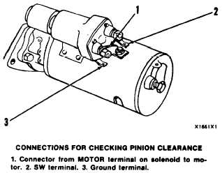
Install the solenoid without connector (1) from
the MOTOR terminal on solenoid to the motor.
Connect a battery, of the same voltage as the
solenoid, to the terminal (2) marked SW.
Connect the other side of battery to ground ter-
minal (3).
MOMENTARILY flash a jumper wire from
the solenoid terminal marked MOTOR to the
ground terminal. The pinion will shift into
cranking position and will remain there until the
battery is disconnected.
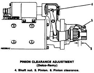
Push pinion towards commutator end to elimin-
ate free movement.
Pinion clearance (6) should be .36 in. (9.1
mm).
7. Adjust clearance by removing plug and turning
shaft nut (4).
1-79