BASIC BLOCK
TM 5-3805-263-14&P-2
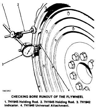
4. The difference between the lower and higher
measurements taken at all four points must not
be more than 0.15 mm (.006 in.), which is the
maximum permissible bore runout (radial ec-
centricity) of the flywheel.
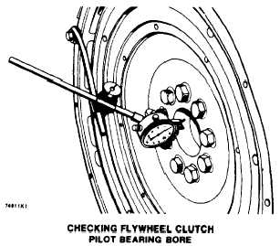
5. Runout (eccentricity) of the bore for the pilot
bearing for the flywheel clutch, must not exceed
0.13 mm (.005 in.).
1-74
TESTING AND ADJUSTING
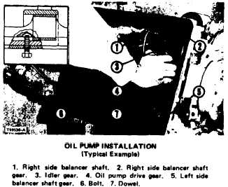
OIL PUMP INSTALLATION
The oil pump can be removed for inspection and
service without removing the timing gear cover.
With the cover in place, timing marks are not easy
to see. Therefore, time both balancer shafts, with
respect to No. 1 piston at TC or compression
stroke, in the following steps.
1.
2.
3.
4.
5.
6.
7.
Rotate the crankshaft to bring No. 1 piston to
TC on compression stroke.
Drive dowel (7) back so it is flush with
mounting face of oil pump mounting bracket.
Rotate both balancer shafts so the flat portion
is away from the oil pan plate. Install bolts (6)
so they enter in countersunk holes in balancer
shafts and limit shaft movement. The bolts
should not be tight against the shaft counter-
sunk hole bottom.
Position oil pump on bottom of engine block
and install the mounting bolts loosely.
Install shims if necessary, between pump
mounting pads and cylinder block to adjust
backlash to .002 to .006 in. (0.05 to 0.15 mm)
between gear (4) and (5) and between gears
(2) and (3).
Drive dowel (7) back in place, through mount-
ing bracket and into cylinder block. Tighten
the mounting bolts.
Remove bolts (6) and check to see that the
countersunk holes are aligned with holes in oil
pan plate when No. 1 cylinder is in TC
position.
Timing mark alignment information shown in
the SPECIFICATIONS is to be used when the
timing gear cover is removed.