ELECTRICAL SYSTEM
TM 5-3805-263-14&P-2
TESTING AND ADJUSTING
2. Cables between the battery, starter and engine
ground must be the correct size. Wires and ca-
bles must be free of corrosion and have cable
support clamps to prevent stress on battery con-
nections (terminals).
3. Leads, junctions, switches and panel instru-
ments that have direct relation to the charging
circuit must give correct circuit control.
4. Inspect the drive components for the charging
unit to be sure they are free of grease and oil and
have the ability to operate the charging unit.
Alternator Regulator (Delco-Remy)
When an alternator is charging the battery too
much or not enough, an adjustment can be made to
the charging rate of the alternator.
Delco-Remy 24V 50A (5S9088 Alternator)
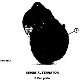
The voltage adjustment screw for the 5S9088
Alternator is located under the end plate.
To adjust the voltage setting on this alternator,
use the procedure that follows:
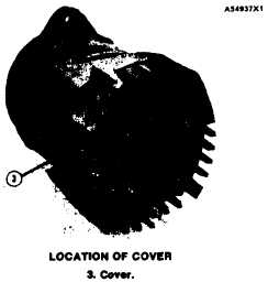
1. Remove end plate (2) and cover (3) from the
alternator.
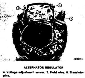
2. Remove the rubber sealant from the adjustment
screw (4).
3. Use a voltmeter to measure alternator voltage
output.
4. Turn adjustment screw (4) counterclockwise to
lower the voltage setting. Turn adjustment screw
(4) clockwise to raise the voltage setting.
5. Put 3S6252 Rubber Sealant on adjustment
screw (4) and install cover (3) and end plate (2).
CAUTION
Make certain that field wire (5) is not located
over transistor pins (6). The pins can make a
hole in the insulation of the wire.
1-76


