BASIC BLOCK
TESTING AND ADJUSTING
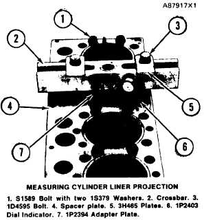
4. Install the 1P5512 Contact Point on dial indica-
tor (6). Put the dial indicator in the 1P2402
Gauge Body. To adjust the dial indicator to zero,
put dial indicator and gauge body on the 1P5507
Gauge. Move the dial indicator until the hand
moves 1/4 turn. Tighten bolt on body to hold the
dial indicator in this position. Turn the dial face
until the zero is in alignment with the hand.
5. Measure the cylinder liner projection as close as
possible to the four corners of the adapter plate
on the liner. The liner projection must be 0.033
to 0.175 mm (.0012 to .0069 in.). The difference
between the four measurements must not be
more than 0.05 mm (.002 in.). The difference in
the average cylinder liner projection of liners
next to each other must not be more than 0.05
mm (.002 in.). The maximum difference in the
average projection for all cylinder liners must
not be more than 0.10 mm (.004 in.).
NOTE: If the liner projection changes from point to
point around the liner, turn the liner to a new position
in the bore. If the liner projection is still not to
specifications, move the liner to a different bore.
installed in the correct position.
Cylinder liner projection can be adjusted by the
removal of material from (machining) the contact
face of the cylinder block with the use of 8S3140
Cylinder Block Counterboring Tool Arrangement.
6. When the cylinder liner projection is correct, put
a temporary mark on the liner and the spacer
plate so at final installation the liner can be
TM 5-3805-263-14&P-2
ADJUSTMENT SHIMS FOR LINER PROJECTION
SHIM THICKNESS, COLOR CODE, AND PART NUMBER
0.18 mm
0.20 mm
0.23 mm
0.38 mm
0.76 mm
(.007 in.) (.008 in.) (.009 in.) (.015 in.)
(.030 in.)
BLACK
RED
GREEN
BROWN
BLUE
8S6045
8S6046
8S6047
8S6048
8S6049
CYLINDER BLOCK
The bore in the block for main bearings can be
checked with the main bearing caps installed
without bearings. Tighten the nuts holding the caps
to the torque shown in the SPECIFICATIONS.
Alignment error in the bores must not be more
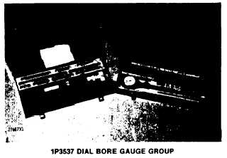
than 0.08 mm (.003 in.). 1P3537 Dial Bore Gauge
Group can be used to check the size of the bores.
FLYWHEEL AND FLYWHEEL HOUSING
Installing Ring Gear
Heat the ring gear to install it. Do not heat to more
than 315°C (600°F). Install the ring gear so the
chamfer on the gear teeth are next to the starter
pinion when the flywheel is installed.
Face Runout (axial eccentricity)
of the Flywheel Housing
Tools Needed:
8S2328 Dial Indicator Group.
If any method other than given here is used, al-
ways remember bearing clearances must be removed
to get correct measurements.
1-71