POWER TRAIN
DISASSEMBLY AND ASSEMBLY
TM 5-3805-263-14&P-2
BRAKE AND WHEEL SPINDLE HOUSINGS
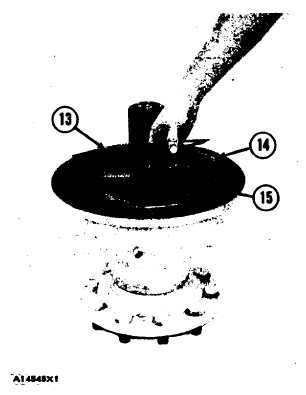
14. Install hub (15) on the wheel spindle.
15. Put clean SAE 30 oil on the discs and on
the disc assemblies.
16. Put discs (13) and disc assemblies (14) in
position in the wheel spindle housing start-
ing with a disc. There are ten discs and nine
disc assemblies. Make sure there is a disc
assembly between each disc.
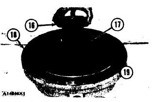
17. Install the O-ring seal in cover (18).
18. Install O-ring seal ( 19) on cover (18). Put
clean grease on the two O-ring seals.
19. Lower the temperature of bearing cup (17)
and install it in cover (18).
20. Install two 5/8”-11 NC forged eyebolts in
cover (18). Fasten a hoist to the eyebolts.
21. Put cover (18) in position on wheel spindle
housing (3). Remove the hoist and the
eyebolts.
22. Install the bolts and the plate that hold
cover (18) to the housing.
23. Install bearing cone (16) on the wheel
spindle and in cover (18).
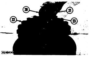
24. Put sprocket (22) in position on the splines
of the wheel spindle.
NOTE: The sprocket for the front brake and wheel
spindle housing must be installed with the teeth
next to the cover. The sprocket for the rear brake
and wheel spindle housing must be installed with
the teeth away from the cover.
25. Put retainer (20) in position on the wheel
spindle without shims. Install bolts (23).
Tighten the bolts to a torque of 35 lb. ft. (4.8
mkg) while turning the housing. Remove the
bolts and the retainer. Measure the distance
between the end of the sprocket and the wheel
spindle. Install the retainer and shims (21)
that are the same thickness as the distance
measured minus .010 to .015 in. (0.25 to 0.38
mm). Install bolts (23) and tighten to 192 ±
10 lb. ft. (260 ± 14 N.m). Install the wire on
the bolts.
end by:
a) install brake and wheel spindle housings
2-52