POWER TRAIN
DISASSEMBLY AND ASSEMBLY
TM 5-3805-263-14&P-2
DRIVE SPROCKETS
REMOVE DRIVE SPROCKETS
Tools Needed
A
5P4204 Spanner Socket
1
start by:
a) remove tandem housings
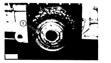
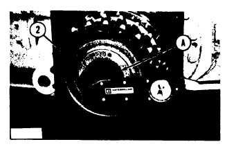
1. Remove nut (1) with tool (A).
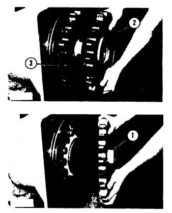
2. Remove sprockets (2) and (3). Weight of
one sprocket is 32 lb. (15 kg).
3. Do Steps 1 through 2 for the other drive
sprockets.
INSTALL DRIVE SPROCKETS
Tools Needed
A
5P4204 Spanner Socket
1
1. Put sprocket (1) in position on the shaft.
Install sprocket (1) with the hub of the
sprocket away from the final drives.
2. Put sprocket (2) in position on the shaft.
Install sprocket (2) with the hub toward the
hub on sprocket (1).
3. Put the nut that holds the sprockets on the
shaft in position on the shaft. Install the
axle in the differential and final drive.
CAUTION: The following procedure must be used
to put the correct amount of preload on the
bearings for the final drives:
A.
B.
C.
D.
E.
F.
G.
H.
4. Do Steps 1 through 3 for the other drive
Tighten the nut to a torque of 100 ±
10 lb. ft. (13.8 ± 1.1 mkg) with tool
(A).
Turn the sprockets to put the bearings
in their seats.
Hit the hub of the sprocket with a large
punch and a hammer.
Do Steps A, B and C until the nut does
not turn when it is tightened.
Loosen the nut.
Tighten the nut to a torque of 50 lb. ft.
(6.9 mkg).
If the nut is in a locking position, install
the cover and the bolts that hold it.
If the nut is not in a locking position,
tighten the nut to the next nearest
locking position. Install the cover and
the bolts.
sprockets.
end by:
2-54
a) install tandem housings


