FUEL SYSTEM
TM 5-3805-263-14&P-2
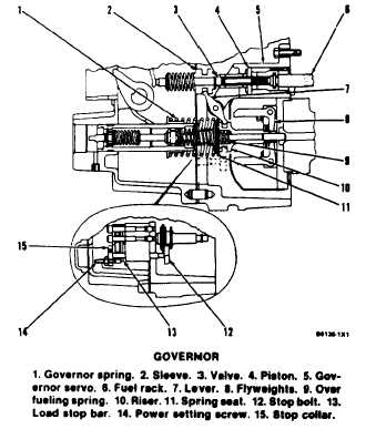
The force of governor spring (1) always pushes to
give more fuel to the engine. The centrifugal (rotat-
ing) force of flyweights (8) always push to get a
reduction of fuel to the engine. When these two
forces are in balance (equal), the engine runs at a
constant rpm.
When the engine is started and the governor is at
the low idle position, over fueling spring (9) moves
the riser forward and gives an extra amount of fuel to
the engine. When the engine has started and begins
to run, the flyweight force becomes greater than the
force of the over fueling spring. The riser moves to
the rear and reduces the amount of fuel to the low
idle requirement of the engine.
When the governor control lever is moved to the
high idle position, governor spring (1) is put in
compression and pushes riser (10) toward the
flyweights. When the riser moves forward, lever (7)
moves sleeve (2) and valve (3) toward the rear. Valve
(3) stops oil flow through governor servo (5) and the
oil pressure moves piston (4) and the fuel rack to the
rear. This increases the amount of fuel to the engine.
As engine speed increases, the flyweight force in-
creases and moves the riser toward the governor
spring. When the riser moves to the rear, lever (7)
moves sleeve (2) and valve (3) forward. Valve (3)
now directs oil pressure to the rear of piston (4) and
SYSTEMS OPERATION
moves the piston and fuel rack forward. This de-
creases the amount of fuel to the engine. When the
flyweight force and the governor spring force become
equal, the engine speed is constant and the engine
runs at high idle rpm. High idle rpm is adjusted by
the high idle adjustment screw. The adjustment
screw limits the amount of compression of the gover-
nor spring.
With the engine at high idle, when the load is
increased, engine speed will decrease. Flyweights (8)
move in and governor spring (1) pushes riser (10)
forward and increases the amount of fuel to the
engine. As the load is increased more, governor
spring (1) pushes riser (10) farther forward. Spring
seat (11) pulls on stop bolt (12). Stop collar (15) on
the opposite end has power setting screw (14) that
controls the maximum amount of fuel rack travel.
The power setting screw moves forward and makes
contact with load stop bar (13). This is the full load
balance point.
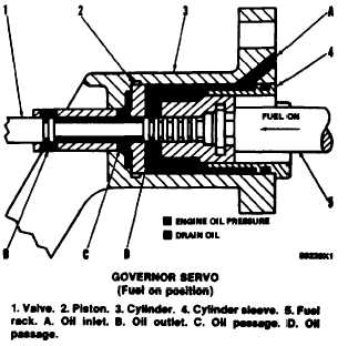
Governor Servo
The governor servo gives hydraulic assistance to
the mechanical governor force to move the fuel rack.
The governor servo has cylinder (3), cylinder sleeve
(4). piston (2) and valve (1).
When the governor moves in the FUEL ON direc-
tion, valve (1) moves to the left. The valve opens oil
outlet (B) and closes oil passage (D). Pressure oil
from oil inlet (A) pushes piston (2) and fuel rack (5)
to the left. Oil behind the piston goes through oil
passage (C), along valve (1) and out oil outlet (B).
1-10