FUEL SYSTEM
SYSTEMS OPERATION
TM 5-3805-263-14&P-2
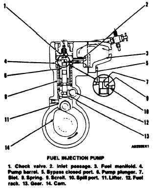
scroll (9) changes the distance the pump plunger
pushes fuel between bypass closed port (5) and spill
port (10) opening. The longer the distance from the
top of the pump plunger to the point where scroll (9)
uncovers spill port (10), the more fuel will be
injected.
To stop the engine, the pump plunger is rotated so
that slot (7) on the pump plunger is in line with spill
port (10). The fuel will now go out the spill port and
not to the injection nozzle.
When the pump plunger is at the bottom of the
stroke, fuel at transfer pump pressure goes into inlet
passage (2), around pump barrel (4) and to bypass
closed port (5). Fuel fills the area above the pump
plunger.
After the pump plunger begins the up stroke, fuel
will be pushed out the bypass closed port until the top
of the pump plunger closes the port. As the pump
plunger travels farther up, the pressure of the fuel
increases. At approximately 690 kPa (100 psi),
check valve (1) opens and lets fuel flow into the fuel
injection line to the fuel injection nozzle. When the
pump plunger travels farther up, scroll (9) uncovers
spill Port (10). The fuel above the pump plunger goes
through slot (7), along the edge of scroll (9) and out
spill port (10) back to fuel manifold (3). This is the
end of the injection stroke. The pump plunger can
have more travel up, but no more fuel will be sent to
the fuel injection nozzle.
When the pump plunger travels down and un-
covers bypass closed port (5), fuel begins to fill the
area above the pump plunger again, and the pump is
ready to begin another stroke.
The amount of fuel the injection pump sends to the
injection nozzle is changed by the rotation of the
Pump plunger. Gear (13) is attached to the pump
plunger and is in mesh with fuel rack (12). The
governor moves the fuel rack according to the fuel
needs of the engine. When the governor moves the
fuel rack, and the fuel rack turns the pump plunger,
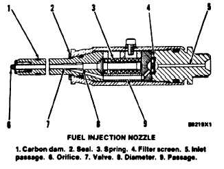
FUEL INJECTION NOZZLE
The fuel injection nozzle goes through the cylinder
head into the combustion chamber. The fuel injec-
tion pump sends fuel with high pressure to the fuel
injection nozzle where the fuel is made into a fine
spray for good combustion.
Seal (2) goes against the cylinder head and pre-
vents leakage of compression from the cylinder. Car-
bon dam (1) keeps carbon out of the bore in the
cylinder head for the nozzle.
Fuel with high pressure from the fuel injection
pump goes into inlet passage (5). Fuel then goes
through filter screen (4) and into passage (9) to the
area below diameter (8) of valve (7). When the pres-
sure of the fuel that pushes against diameter (8)
becomes greater than the force of spring (3), valve
(7) lifts up. When valve (7) lifts, the tip of the valve
comes off of the nozzle seat and the fuel will go
through the nine 0.20 mm (.008 in.) orifices (6) into
the combustion chamber.
The injection of fuel continues until the pressure of
fuel against diameter (8) becomes less than the force
of spring (3). With less pressure against diameter
(8). spring (3) pushes valve (7) against the nozzle
seat and stops the flow of fuel to the combustion
chamber.
1-7


