GENERAL INFORMATION
SYSTEMS OPERATION
TM 5-3805-263-14&P-2
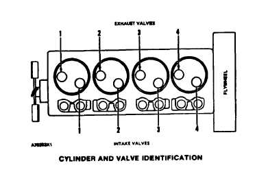
ENGINE DESIGN
Bore ..................................................................
4.75 in. (120.7 mm)
Stroke
................................................................
6.0 in. (152.4 mm)
Number of Cylindera
...................................................................
4
Firing Order (Injection Sequence) . . . . . . . . . . . . . . . . . . . . . . . . . . . . . . . . . . . . . . . 1,3,4,2
Direction of Flotation
Cylinder Arrangement . . . . . . . . . . . . . . . . . . . . . . . . . . . . . . . . . . . . . . . . . . . . . . . . . .
*in-line
(when seen from flywheel end). . . . . . . . . . . . . . . . . . . . . . . . . . . . . . . . .
Counterclockwise
*No. 1 Cylinder Is Opposite Flywheel End.
1-5