TM 5-3805-263-14&P-3
DISASSEMBLY AND ASSEMBLY
TRANSMISSION CONTROL
13
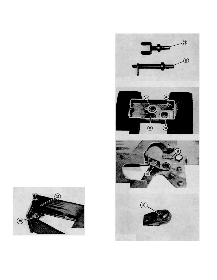
Remove keys and bearings from shafts (25) and
(26).
14
Put identification on levers as to their location in
(28) and (29). Two spiral snap rings are used as
a seat for bearings (27) and (30). These rings can
be removed.
15
Remove two bolts (32) and bracket assembly.
(31) from plate.
16
Remove bearing (33) from bracket.
17
Remove cotter pin, pin (35), two washers and the
rod and spring assembly (34) from plate.
4-78


