TM 5-3805-263-14&P-3
DISASSEMBLY AND ASSEMBLY
BLADE LIFT LOCK CHECK AND RELIEF VALVE
AND LOCK CHECK VALVES
DISASSEMBLE BLADE LIFT LOCK CHECK AND
RELIEF VALVE AND LOCK CHECK VALVES
start by:
a) remove blade lift lock check and relic valve
b) remove blade sideshift, blade tip, circle drive,
wheel lean, articulation, blade lift or centershift
lock check valve
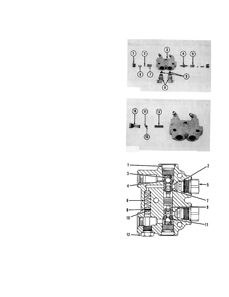
1. Remove adapters (8) and chokes (9) from body
(3). Remove the O-ring seals from the adapters
NOTE: Only the blade lift lock check and relief valve and
the articulation, blade lift and centershift lock check
valves are equipped with adapters and chokes.
TYPICAL EXAMPLE
2. Remove plug (I), spring (6) and ball (2) fror end of
the body. Remove the O-ring seals from the plugs.
3. Remove piston (4) and seat (5) with a .25 in.
(6.mm) diameter brass rod and a hammer.
Remove seat (7) with a .69 in. (17.5 mm) diameter
bras rod and a hammer.
CAUTION
Be extra careful not to cause damage to the piston
and the seats during disassembly of the valve.
4. Remove plug (10), valve (11), shims (13) and
spring (12) from the body (blade lift lock check and
relief valve only).
ASSEMBLE BLADE LIFT LOCK CHECK AND RELIEF
BLADE LIFT LOCK CHECK
VALVE AND LOCK CHECK VALVES
AND RELIEF VALVE
CAUTION
Be extra careful not to cause damage to the piston
and the seat, during disassembly of the valve.
1. Install seat (I 1) in the body with a .69 in. (17.5
mm) diameter rod and a hammer. Install piston (9)
in the body and seat (11). Install seat (7) in the
body with a .69 in. (17.5 mm) diameter rod and a
hammer. Check to see that the piston falls freely
through the seat. Check both ends of the piston.
2. Install new O-ring seals on the plugs. Install ball
(4), spring (3) and plug (1) in each end o the valve.
Tighten the plugs to a torque of 55 + 5 lb.ft. (75 + 7
N.m).
3. Install new O-ring seals on the adapters. Install
chokes (2) and adapters (5) in the body Tighten
the adapters to a torque of 55 + 5 lb.ft (75 + 7
N.m).
NOTE: Only the blade lift lock check and relief valve and
the articulation, blade lift and the centershift lock check
end by:
valves are equipped with adapters and chokes.
a) install blade lift lock check and relief valve.
4. Install spring (6), shims (8), valve (10) and plug
b) install blade sideshift, blade tip, circle drive,
(12) in the body (blade lift lock check and relief
wheel lean,blade lift, articulation or centershift
valve only).
lock check valve.
3-164


